
Original FWD Atto 3 replacement parts
BYD Atto 3 Cooling & Heat-Pump Circuits
Identify the Atto 3 coolant or refrigerant circuit before comparing thermal components.
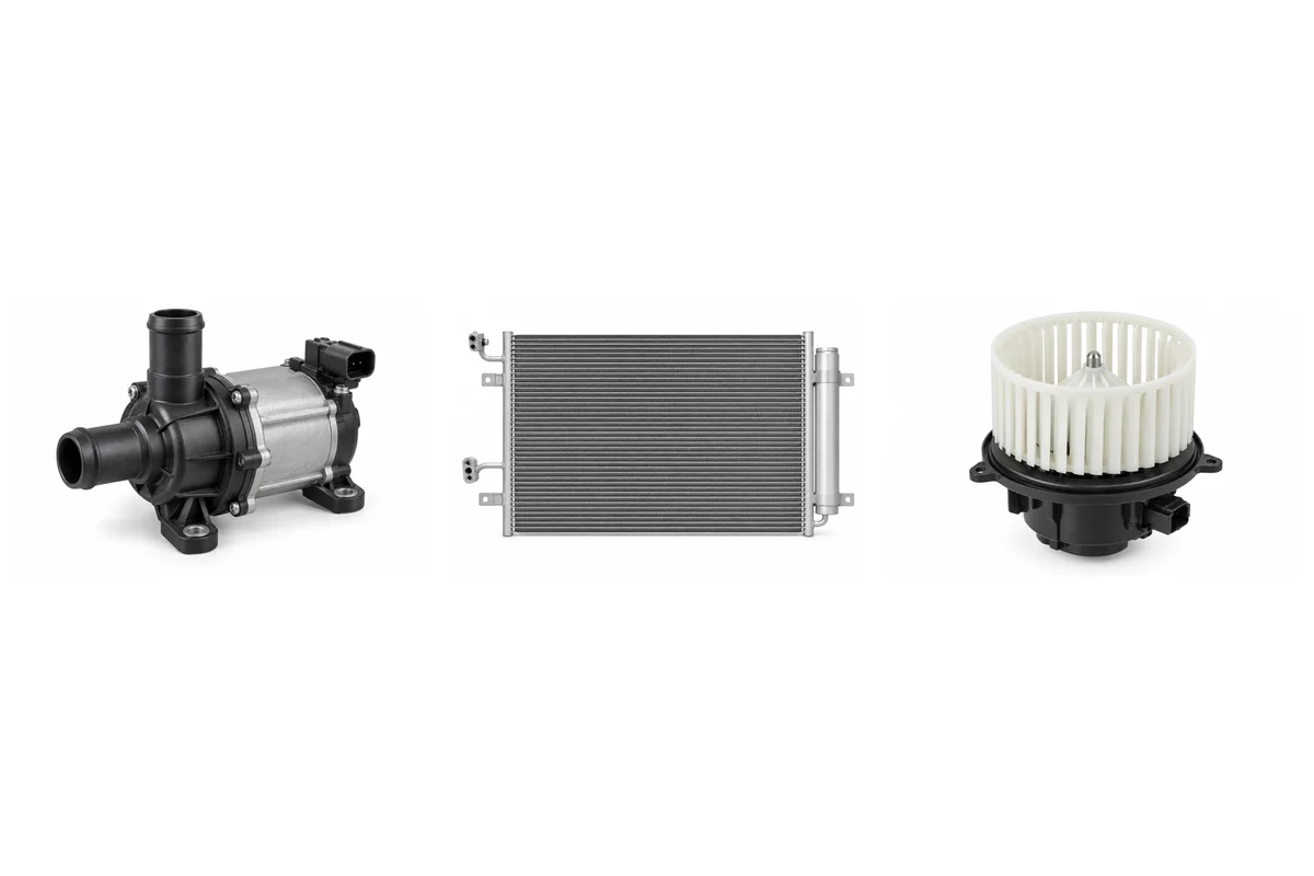
Name the circuit before selecting a part
The original vehicle uses electric-drive cooling and heat-pump climate equipment; engine-cooling and belt-driven compressor references do not identify these assemblies. Record the installed component label and hose or pipe connections.
Separate coolant heat exchange from refrigerant equipment
A motor coolant radiator and an A/C condenser can sit in the same front pack but carry different fluids and use different connections. The cabin evaporator belongs to the refrigerant circuit. Compare the actual port blocks and mounting tabs instead of ordering all front heat exchangers under one radiator description.
Identify pumps, reservoirs and routing valves together
Name the motor, battery or other verified circuit, then record pump voltage and control interface, reservoir branches and valve port routing. Similar housings do not establish the same flow or calibration. Keep ports capped and do not assume that a thermal valve can be substituted by matching its port count.
Keep cabin airflow components distinct
The blower motor moves cabin air while its control module regulates operation. Compare impeller depth, HVAC housing and steering-market packaging separately from the control plug. Outside-air temperature and refrigerant-pressure sensors have different measurements and cannot be selected from connector resemblance.
Respect the electrical and refrigerant boundary
Keep heat exchangers, low-voltage circulation and cabin components on individually identified order lines. High-voltage compressors, traction batteries and inverters require a separate technical and handling assessment. Qualified EV and refrigerant technicians must determine safe service procedures, pressure requirements and correct refrigerant for the actual vehicle.
Connected assembly checks
Match the Cabin Air Filter to its tray while checking the Blower Motor and Blower Control Module as separate cabin-airflow assemblies.
Compare the Motor Cooling Radiator and Cooling Fan Assembly mounts with the Radiator Support before combining a front cooling-pack order.
Before combining a Electric Coolant Pump, Coolant Reservoir and Coolant Control Valve, confirm that each belongs to the intended coolant circuit; similar fittings do not establish common routing.
Components to identify separately
| Assembly | Selection evidence |
|---|---|
| Motor Cooling Radiator | Coolant circuit, core dimensions, ports and mounting tabs |
| Cooling Fan Assembly | Shroud outline, motor control, connector and cooling-pack mounts |
| Electric Coolant Pump | Named coolant circuit, low-voltage rating, port layout and control plug |
| Coolant Reservoir | Motor or battery coolant circuit, molded shape, hose branches and cap |
| Coolant Control Valve | Circuit function, port count, hose orientation and control interface |
| A/C Condenser | Heat-pump refrigerant circuit, port blocks, core size and receiver contents |
| A/C Evaporator | HVAC case, steering market, refrigerant connections and valve contents |
| Blower Motor | HVAC case, wheel rotation, wheel height and electrical connector |
| Blower Control Module | HVAC control version, connector pins, heat sink and mounting flange |
| A/C Pressure Sensor | Refrigerant circuit, pressure range, thread and connector keying |
| Ambient Temperature Sensor | Front-body mounting, probe shape, connector and wiring reference |
Continue the parts list
Return to the Atto 3 system directory for other assemblies. Use the OE and VIN checklist for missing identification and the quotation guide for commercial and freight records.
Auto parts inquiry
Send the vehicle and part evidence.
Include brand, full model, year, engine or EV drivetrain, OE/material code, quantity, destination and packing request. You can attach a list or old-part photos.