
Tiggo 7 / Pro / Pro Max • Petrol, MHEV and PHEV identified separately
Chery Tiggo 7 Chassis, Brakes & AWD Selection
A brake or chassis request needs corner, fitted hardware and driven-axle information.
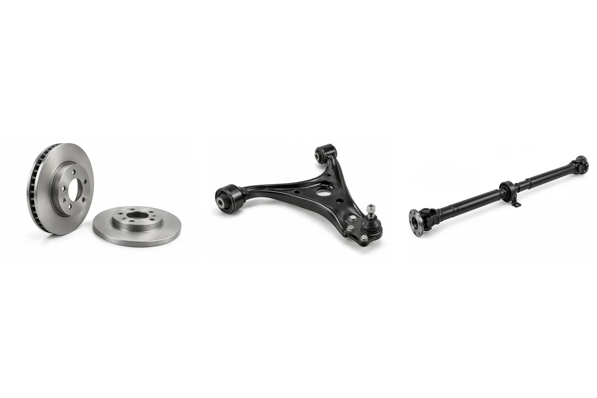
Begin with the actual corner and axle
Wheel size and an EPB switch do not select pads, rotor dimensions or carrier geometry. Keep removed backing plates, rotor measurements, caliper marks and sensor routing together before choosing an axle set or mixed corner order.
Identify suspension independently from drive naming
The documented Australian MY26 petrol and CSH examples use front struts and rear multi-link suspension despite being FWD. Do not assume FWD means torsion beam. Earlier market and Pro Max vehicles must retain their actual arms, rear carrier and damper geometry rather than inheriting a related model description.
Locate each arm, joint and support
Front lower arms, rear lateral members and trailing arms have distinct mounting and load paths. Confirm whether the requested joint is independently replaceable and which taper or retention it uses. Strut mounts, bearings and springs also need separately agreed contents; spring load grade is not established by free height alone.
Separate wheel-end and shaft contents
A bare hub flange, bearing and equipped wheel end are different quotations. Preserve the encoder and knuckle interfaces with the actual corner. Front and AWD rear CV shafts follow the installed transmission or rear output, including working length and spline; a centre-support bearing number does not approve a complete axle.
Confirm mechanical AWD before the longitudinal list
Only an identified mechanical AWD vehicle justifies a propeller shaft, transfer/output unit and rear differential. Retain their labels, flange patterns, gearing and coupling contents together. A Pro Max badge, multi-link rear axle or plug-in hybrid description does not select these assemblies independently of the actual drivetrain.
Keep assist and sensor systems distinct
EPS does not locate an assist motor on the rack, and hybrid braking equipment cannot be selected from a conventional vacuum-booster photograph. Retain the installed steering and hydraulic labels. Wheel-speed pickups, TPMS transmitters and parking-brake actuators require different electrical or mechanical interface records.
Connected selection questions
Compare brake pads against the fitted brake discs and axle.
Preserve the brake caliper marking when agreeing pad, carrier and equipped-caliper contents.
Match the brake caliper port to the routed brake hose at the same wheel corner.
The motor-only parking brake actuator needs the rear-caliper drive interface.
Identify the brake master cylinder with its installed brake booster assist system.
A brake hose request still retains its own corner and union record.
Assemblies to identify separately
| Assembly | Application | Selection record |
|---|---|---|
| Brake Pads | Installed axle and disc brake package | Axle, backing plate, caliper, shims and friction grade |
| Brake Discs | Actual wheel corner and fitted brake hardware | Diameter, thickness, hat height, centre bore and venting |
| Brake Caliper | Exact hydraulic corner and parking-brake design | Casting, carrier, piston, fluid port and actuator interface |
| Brake Master Cylinder | Confirmed hydraulic brake-system identity | Cylinder label, bore, ports, mounting and reservoir seat |
| Brake Booster | Installed assist assembly; hybrid checked independently | Assist type, label, stud spacing and pushrod interface |
| Brake Hose | Exact hydraulic corner and installed routing | Union threads, fitting angles, brackets and routed length |
| ABS Wheel Speed Sensor | Identified wheel pickup and encoder system | Corner, full marking, socket, lead route and pickup depth |
| TPMS Sensor | Installed pressure-monitoring radio system | Sensor label, frequency, protocol, valve and wheel seat |
| Parking Brake Actuator | Motor-only request for the actual rear caliper | Caliper label, output drive, socket and fastening |
| Shock Absorber / Strut | Actual axle/corner and suspension package | Side, mounting, spring seat, stroke and load specification |
| Strut Mount | Identified upper strut or damper support | Stud pattern, central sleeve, bearing and spring seat |
| Coil Spring | Axle and actual suspension/load class | Spring marking, ends, dimensions and vehicle load record |
| Control Arm | Exact front or rear multi-link arm location | Axle/side, mounting centres, bushes and joint contents |
| Ball Joint | Only a confirmed independently replaceable joint | Arm retention, stud taper, mounting and fixing |
| Tie Rod End | Installed rack and inner/outer steering joint | Rack marking, thread, offset, adjustment and taper |
| Stabilizer Link | Identified anti-roll bar and axle position | Joint-centre length, stud angle and motion clearance |
| Wheel Hub / Bearing | Actual front or rear wheel-end format | Flange, bearing contents, spline and ABS encoder |
| CV Axle / Drive Shaft | Identified driven corner and gearbox/drive unit | Side, spline, working length, joints and seal land |
| Steering Rack | Actual steering market and assist layout | Rack label, mounting, ratio, joints and interfaces |
| Engine Mount | Exact engine-side support and mounting position | Engine label, bracket, position and mount design |
| Transmission Mount | Identified MT/CVT/DCT/DHT support | Gearbox label, body pickups, bracket and isolator |
| Subframe | Actual front carrier or rear multi-link support | Axle, build, suspension pickups and drivetrain interfaces |
| Steering Knuckle | Exact wheel upright and carrier | Corner, bearing format, strut, arm and brake mounts |
| AWD Propeller Shaft | Confirmed mechanical AWD longitudinal shaft only | Vehicle/gearbox, flange patterns, length, joints and supports |
| AWD Transfer Unit | Installed mechanical AWD power-transfer unit | Gearbox pairing, casting, ratio, output and mounting |
| AWD Rear Differential | Confirmed mechanical rear final-drive assembly | Unit label, ratio, coupling, flanges and carrier mounts |
Continue the order
Return to the Tiggo 7 grouped parts directory. For quantities and commercial fields, use parts-list quotation preparation rather than inferring price or stock from a reference number.
Auto parts inquiry
Send the vehicle and part evidence.
Include brand, full model, year, engine or EV drivetrain, OE/material code, quantity, destination and packing request. You can attach a list or old-part photos.